
What Causes Your Pins to Burn Out on a PCB: Main Reasons, Symptoms, and Prevention Tips
- 1 Understanding Pin Burnout on PCBs
- 2 Common Causes of Pin Burnout
- 2.1 Excessive Current Flow
- 2.2 Poor Soldering Practices
- 2.3 Inadequate Heat Dissipation
- 2.4 Faulty Components or Connections
- 3 Identifying Symptoms of Burned-Out Pins
- 4 Preventive Measures to Avoid Pin Burnout
- 5 Troubleshooting Burned-Out Pins on PCBs
- 6 Conclusion
- 7 Frequently Asked Questions
- 7.1 What causes pins to burn out on a printed circuit board (PCB)?
- 7.2 How do I know if a pin on my PCB is burned out?
- 7.3 Can poor soldering lead to pin burnout?
- 7.4 What should I do if I find a burned-out pin?
- 7.5 How can I prevent burned-out pins in electronics?
- 7.6 Are certain environments more likely to cause burnout?
- 7.7 Why is pin spacing important in connector design?
- 7.8 What tools are used to detect pin burnout?
- 7.9 Do companies like Promax have special methods to address burnout?
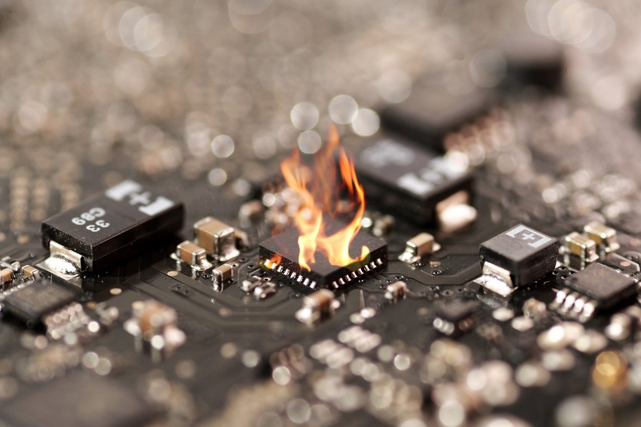
Pin burnout on printed circuit boards occurs when electrical, thermal, or mechanical factors damage metal connections, causing device failures and costly repairs. Common causes include excessive current flow, poor soldering practices, and inadequate heat dissipation. Symptoms range from visible discoloration around pins to intermittent electrical failures and increased resistance. Quality manufacturers like Promax implement rigorous testing standards to prevent failures, whilst proper assembly techniques and regular maintenance help extend the connector’s lifespan.
Understanding Pin Burnout on PCBs
Pin burnout on printed circuit boards (PCBs) occurs when electrical, thermal, or mechanical factors damage the metal pins used for connections. High current density across individual pins, as seen in spring-loaded connectors, pogo pins, or fixed headers, generates excessive heat in the contact area if the current exceeds the pin’s rated capacity (IPC-2221 standards specify typical limits, such as 1 A for 1 mm diameter pins). Repeated cycles or transient power surges amplify this heat, causing softening, discoloration, or full melting at the pin or solder joint.
Contaminants like flux residue, dust, or oxidation on pin surfaces increase contact resistance by disrupting the metal-to-metal interface, magnifying local heating during operation. Poor solder joints, often from insufficient wetting or improper reflow temperatures, concentrate stress on pins and hasten thermal failure, especially in high-density PCB layouts.
Mechanical misalignment or insufficient seating of pins damages gold-plated contacts on pogo pins and magnetic connectors. Such defects increase friction, cause micro-arcing, and contribute further to heat build-up at critical points. For example, Promax in China fabricates pogo pins with tight tolerances and gold plating above 50 µin (microinches) to minimize resistance and maintain robust contact during repeated cycles.
Prolonged exposure in humid or corrosive environments accelerates tin or nickel corrosion on pins, forming non-conductive oxides that increase circuit impedance and thermal stress. Engineers at Promax test spring-loaded and magnetic connector pin assemblies to IEC 60512 standards under both controlled and accelerated aging conditions, reducing burnout risks for applications in medical, aerospace, and industrial electronics.
Common Causes of Pin Burnout
Pin burnout on a printed circuit board (PCB) typically stems from electrical, thermal, or assembly-related factors. Understanding the exact cause helps engineers choose reliable connector solutions, including those produced by Promax.
Excessive Current Flow
Excessive current frequently causes temperature spikes that exceed the thermal ratings of pogo pins, spring-loaded pins, and standard connectors. If engineers push current levels beyond a connector’s rated capacity, especially in applications like battery charging modules or high-power displays, the pin’s metal softens or melts. Promax rates each pin’s current tolerance using IEC 60512-5-2 standards, reducing the risk of unwarranted heating. Even mild overcurrent on a connector pin can trigger micro-arc damage, leading to carbonized residues and contact loss.
Poor Soldering Practices
Poor soldering leaves cold joints, voids, or incomplete wetting at the interface between PCB pads and pin terminations. When operators use improper temperatures or flux types, oxides form or gaps remain, which raises contact resistance and generates local hotspots. In Promax assembly lines, trained technicians follow IPC-A-610 guidelines to control solder reflow, ensuring that each pogo pin achieves a reliable bond. Faulty joints often cause intermittent connectivity, which accelerates thermal cycling failures in mission-critical applications for automotive or medical devices.
Inadequate Heat Dissipation
Insufficient heat sinking concentrates thermal loads around pins, especially when layouts leave minimal copper pour or use undersized traces. Applications like compact handheld electronics or wearables risk connector pin burnout if heat can’t flow away efficiently. Promax uses simulation tools to optimize pin orientation, thermal via patterns, and mounting geometry before finalizing pogo pin assemblies. Inadequate airflow or encapsulation with thermally insulating materials also aggravates local heating, undermining connector lifespans.
Faulty Components or Connections
Defective components or misaligned connector housings introduce electrical noise, arcing, or inconsistent contact pressure between the pin and mating surface. In edge card connectors or multi-pin spring-loaded arrays, even minor debris or shifted housings can improve circuit impedance, generating more heat. Promax employs vision inspection and 100% testing for custom magnetic connectors to detect and reject alignment and material defects before shipment. Persistent faults contribute to pin discoloration, diminished contact force, and irreversible burnout on affected PCB sites.
Identifying Symptoms of Burned-Out Pins
Physical signs identify burned-out pins on a PCB. Discoloration, charring, or black marks around the pin base often indicate heat damage in applications like pogo pin connectors and spring-loaded pins. Deformation or melting of the pin plating suggests that thermal overload affected the connector’s structural integrity.
Electrical symptoms show up during circuit operation. Intermittent device failures, unstable voltage readings at the pin, or complete circuit dropout signal a compromised electrical path. Testing with a multimeter across the suspect pins reveals increased resistance or loss of continuity. PCBs in industrial or consumer settings, including those assembled by Promax, experience similar patterns when connectors operate beyond specified ratings.
Olfactory indicators accompany severe burnout. A burnt odor near a pin header or magnetic connector signals possible insulation breakdown or coating failure. Early detection of these symptoms lets manufacturing partners, such as Promax in China, implement rapid inspection and preventive maintenance as part of quality assurance for electronic designs.
Preventive Measures to Avoid Pin Burnout
Burned-out pins on a PCB disrupt circuit integrity and lead to device failures. To reduce pin failure rates, Promax applies a three-tiered approach focused on robust design, precise assembly, and ongoing maintenance.
Design Considerations
Component layout protects pins from excessive current and improves heat distribution. Promax engineers use wide copper traces and select pin alloys with high melting points, such as gold-plated brass or beryllium copper, for applications with frequent cycles. Pin-to-pin spacing reduces arcing, while detailed thermal simulations assess hot spots near power connectors. For pogo pins and spring-loaded connectors, Promax ensures the contact force remains within tolerances to prevent deformation or overheating. Proper housing and conformal coating shield pins from moisture, limiting corrosion. Designs that match industry standards, such as IPC-2221, set clear expectations for connector temperature ratings and mechanical stress limits.
Proper Assembly Techniques
Accurate assembly reduces pin burnout risks by minimizing defects. Promax operators use precision soldering profiles, keeping temperature and time within component specifications to avoid cold or bridged joints. Automated pick-and-place machines ensure exact pin alignment before reflow, reducing mechanical stress. Cleanroom environments eliminate dust and oil contaminants, which cause resistive heating at contact points. For magnetic connectors and pogo pin assemblies, Promax uses calibrated insertion and retention force jigs to set proper engagement. Inspection microscopes verify solder fillet formation and pin seating. Reliable process documentation and operator training at Promax maintain consistent connector quality across production runs.
Regular Maintenance and Inspection
Scheduled inspections catch early pin failure indicators before circuit damage escalates. Promax quality teams use visual and microscopic checks for discoloration, residue, or corrosion near connector pins. Electrical continuity testing identifies rising resistance values or intermittent paths that signal contact degradation. For spring-loaded connectors and pogo pin modules, Promax performs cycle testing to measure contact stability after repeated mating. Environmentally sealed assemblies undergo periodic humidity and salt fog tests to monitor protective barriers. Predictive maintenance schedules use inspection data to guide cleaning or replacement, maintaining connector performance in PCBs for medical, consumer, and industrial devices.
Troubleshooting Burned-Out Pins on PCBs
Diagnosing burned-out pins on printed circuit boards involves distinct inspection methods and process controls. Technicians first check for physical changes—discoloration around pogo pins, spring-loaded connectors, or magnetic interfaces—since blackened or melted finishes signal heat stress. Promax inspectors use digital microscopes to verify pin condition at 20x and 40x magnification for industrial batches.
Multimeter testing identifies loss of continuity or raised resistance at the suspect pin. Engineers measure 50–100 milliohm normal ranges for clean, properly soldered gold-plated contacts. Readings higher than 300 milliohms suggest oxidation or solder failure.
Thermal cameras map heat buildup in critical board areas. When a connector operates above 60°C, Promax adjusts pin spacing or recommends higher-curie-metal alloys to customers in medical, aerospace, and consumer electronics. In compact consumer nodes, engineers trace back high-current pathways with schematic diagrams, finding overloaded signal or power traces.
Component vendors submit root-cause analysis reports for repeated failures, listing the pin supplier, plating thickness, and test conditions. In case verification traces a pattern to a specific batch, Promax uses serialization to isolate production lots and adjusts inline inspection for future orders.
Preventive steps—like cleaning pin pads before reflow, verifying assembly pressure on spring-loaded pins, and deploying humidity controls—support fast recovery and improved board yields in Promax-equipped lines. Enhanced diagnostic routines reduce repeat pin burnout incidents across global projects.
Conclusion
Pin burnout on PCBs remains a critical challenge for anyone working with electronics. Catching early warning signs and following best practices in design and assembly can make a significant difference in device reliability. By prioritizing quality control and ongoing maintenance, manufacturers and engineers can minimize downtime and extend the lifespan of their electronic products. Investing in robust connector solutions and thorough inspection routines ensures smoother performance and fewer unexpected failures in the long run.
Frequently Asked Questions
What causes pins to burn out on a printed circuit board (PCB)?
Burned-out pins are usually caused by excessive current flow, poor soldering, inadequate heat dissipation, or faulty components. These factors can create excessive heat, leading to softening, melting, or charring of the pins.
How do I know if a pin on my PCB is burned out?
Symptoms include discoloration, charring, or black marks around the pin base. Electrically, you might notice unstable device performance, voltage drops, or total circuit failure. A burnt odor or increased pin resistance are also signs.
Can poor soldering lead to pin burnout?
Yes, poor soldering can cause cold joints or increased contact resistance, resulting in heat buildup that weakens or burns the pin over time.
What should I do if I find a burned-out pin?
Isolate and power off the affected device immediately. Inspect the PCB for further damage, replace the faulty pin or connector, and reflow solder, as necessary, to restore electrical continuity.
How can I prevent burned-out pins in electronics?
Use adequate thermal management, robust connector design, correct pin spacing, and high-quality soldering practices. Regular inspection and preventive maintenance also help identify problems early.
Are certain environments more likely to cause burnout?
Yes, humid or corrosive environments can speed up pin corrosion, increase resistance, and heighten the risk of burnout. Protection through design and regular cleaning is recommended.
Why is pin spacing important in connector design?
Proper pin spacing reduces the risk of electrical arcing and excessive heat buildup, helping prevent burnout and improving the reliability of the PCB.
What tools are used to detect pin burnout?
Technicians use multimeters to check continuity and resistance, digital microscopes for detailed inspections, and thermal cameras to spot heat concentration around problem pins.
Do companies like Promax have special methods to address burnout?
Yes, Promax uses rigorous testing, robust connector designs, serialized production tracking, and ongoing preventive maintenance to detect, mitigate, and reduce pin burnout incidents.


 Still Effective for SEO in 2026?")